Student Projects
VM495
Modal Analysis of a Cold-Rolled Steel Plate
Team Members: Jiaxi Chen, Yunqi Liu, Zhejun Liu, Shenhao Xie, Xiaochen Zhu
Project Video
Team Members
Team Members:
Jiaxi Chen, Yunqi Liu, Zhejun Liu, Shenhao Xie, Xiaochen Zhu
Project Description
INTRODUCTION
Resonant frequencies are frequencies where the structure vibration amplitude is more pronounced. Modal analysis is used to predict the deformation for a given structure in the frequency domain. In the manufacturing industry, it is often applied to a prototype before the design is put into mass production, sometimes as an alternative or a complement to finite element analysis (FEA).
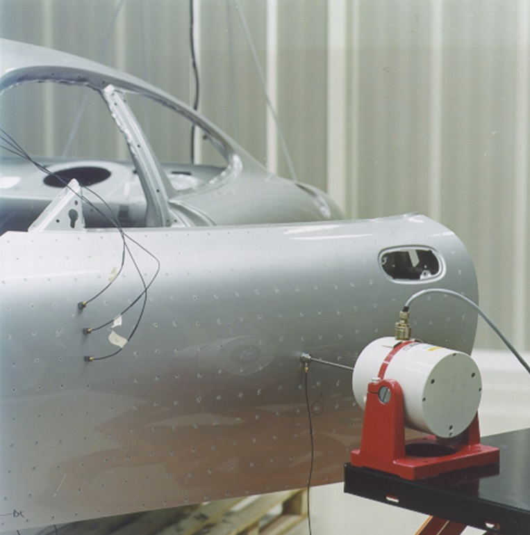
Fig. 1. Modal analysis on a car door.
Theory
- For a vibration system:
[𝑀]{𝑥 ̈(𝑡)}+[𝑐]{𝑥 ̇(𝑡)}+[𝑘]{𝑥(𝑡)}={𝐹(𝑡)}
𝑀=mass, 𝑐=damping, 𝑘=stiffness - After fast Fourier transform (FFT):
{𝑥}=[𝐻]{𝐹}
[𝐻]=frequency response function (FRF) matrix
Objectives
- Perform modal analysis on a cold-rolled steel plate
- Build experimental model using modal analysis
- Build theoretical model using FEA in SolidWorks
- Compare the results of the two models at various mode shapes
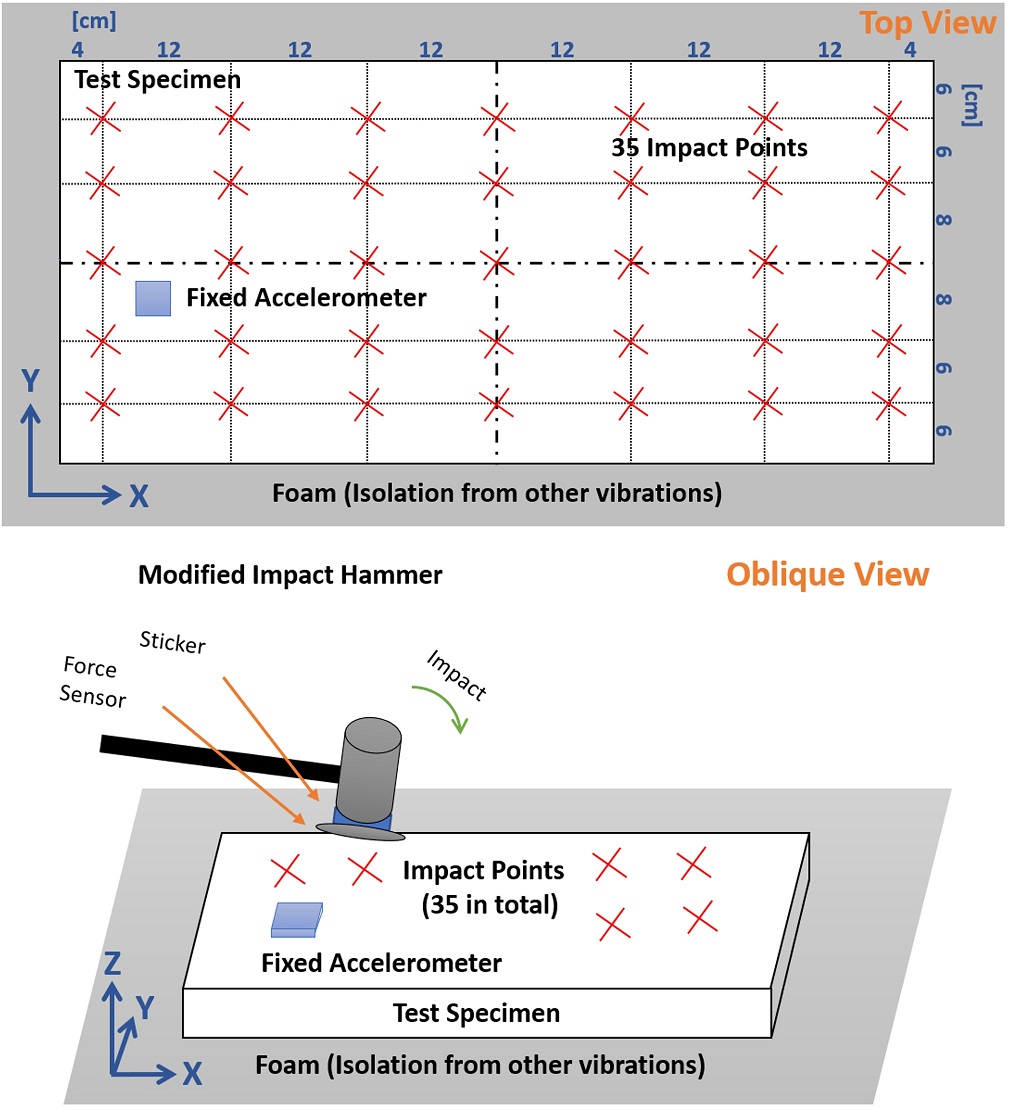
Fig. 2. Experimental setup.
Results & Analysis
- 35 FRFs obtained using FFT in MATLAB
- Perform integration to find displacements at modes
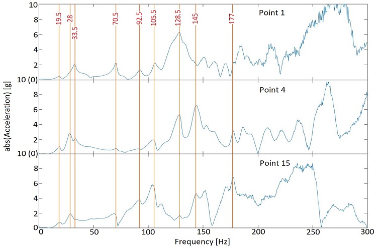
Fig. 3. FRFs at points 1, 4, and 15.
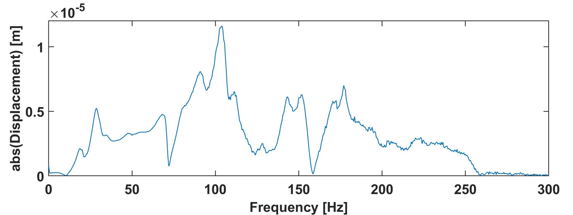
Fig. 4. Vertical displacement at point 15.
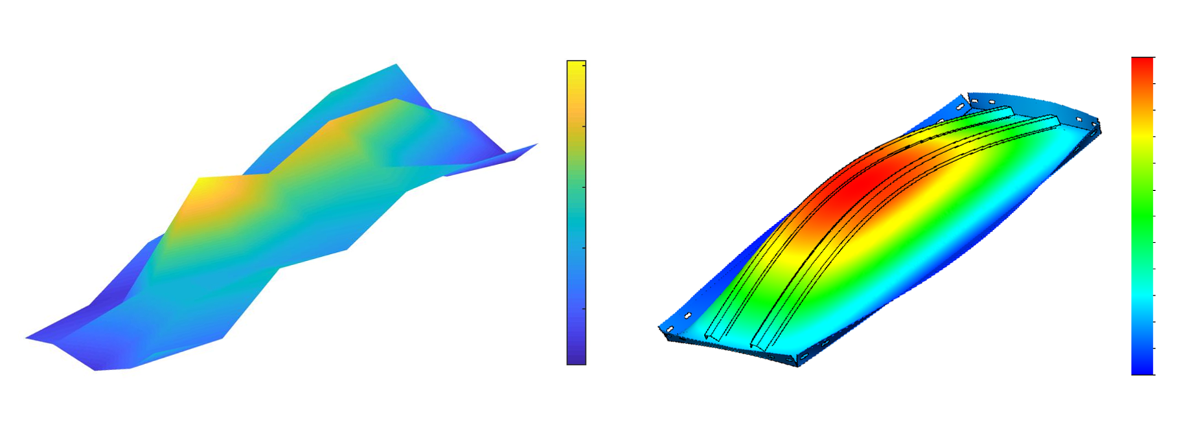
Fig. 5. Simulations in MATLAB at 70.5 Hz (left) and SolidWorks at 98.3 Hz (right).
Summary
In this project, we performed modal analysis on a cold-rolled steel plate and compared the results with those using FEA. Although limitations in equipment and other factors caused inconsistencies between the two models, the experiment itself showed repeatable results within a reasonable uncertainty range.
Acknowledgement
Instructors: Chien-Pin Chen, Kwee-Yan Teh
Reference
K. Ahlin and U. Carlsson, Engineering Vibrations. KTH Engineering Science, 2009.
https://commons.wikimedia.org/wiki/File:Modal_testing-detail.tif