Student Projects
VG100
“Green” Cooling Cup
Team Members: Duanxie Shen; Feiyang Xu; Haoquan Zhou; Sizhe Zhou; Yichu Xie
Project Video
Team Members
Team Members:
Duanxie Shen; Feiyang Xu; Haoquan Zhou; Sizhe Zhou; Yichu Xie
Instructor:
Dr. Qiang Zhang, Dr. Irene Wei
Project Description
Problem Statement
Green energy is believed to be cure of current world energy crisis. But most cooling cups on the market use external electricity. The purpose of this project is to design a “green cooling cup”, which can effectively cool down hot water by using its heat as the only energy source.
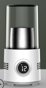
Fig. 1 Electricity Cooling Cup
Design Concept
- Energy Source: Equipped with heat sinks, the thermal-electric (TE) modules convert hot water’s internal energy to electricity based on Seeback effect.
- Stir Apparatus: Two rotating magnetics drive the stir bar inside the cup to make the water move.
- Fan Design: With special design including vortex generators and a special tail, the fan is used to direct the air flow to maintain the temperature difference in TE modules as well as cool the cup.
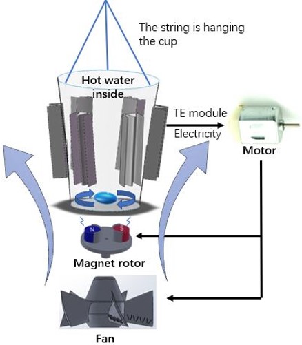
Fig. 2 Concept Diagram
Cooling System
Our cooling system consist of three functional parts: fan, magnet rotor and lifting device.
- Fan: Placed at the bottom of the cup, directing the air upwards to cool down the heat sinks to make the TE functional, and more efficient with vortex generators on it.
- Magnet Rotor: creating a rotating magnet field to make the stir bar in the cup, and consequently hot water, rotates. This branch-circuit will be cut off by switch when the rotor stops operating.
- Hanging Structure: consisting of a supporter and several string to hang the cup in pendent, leaves more space for air to go upward.
Particularly, six TE modules are in series connection, while the fan and the magnet rotor are in parallel connection.
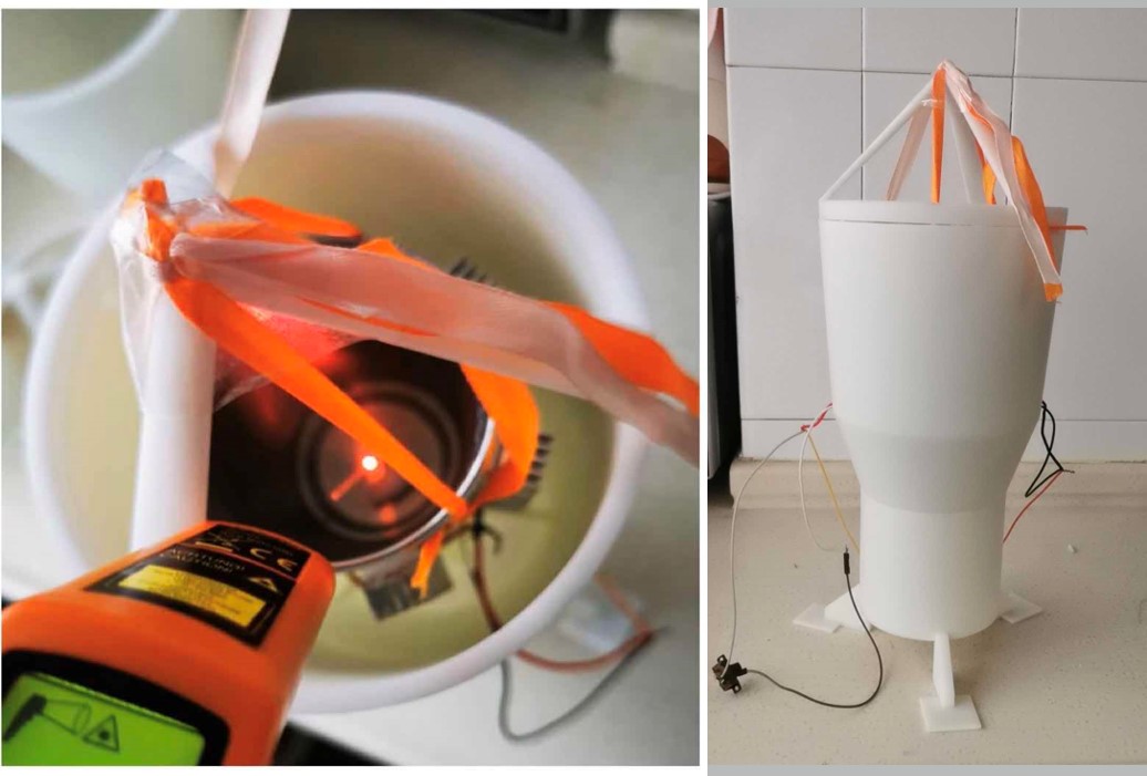
Fig.3 The Real-life Photograph
CFD Simulation
A SolidWorks fan model is built and put into Ansys for simulation. The result shows that the air flow rotates rigorously after passing the fan.
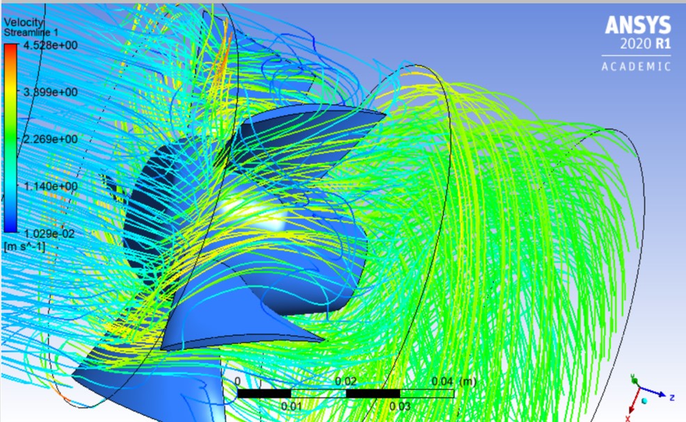
Fig. 4 Simulation Result
Performance Measurement
According to the graph, the cooling system reaches its highest efficiency after it starts for a while. That’s because it takes some time for magnet rotor to create an eddy and make the whole cup of water rotate. The decreasing speed of the temperature drops a little at about two minutes because the rotating speed of the magnet rotor slows down.
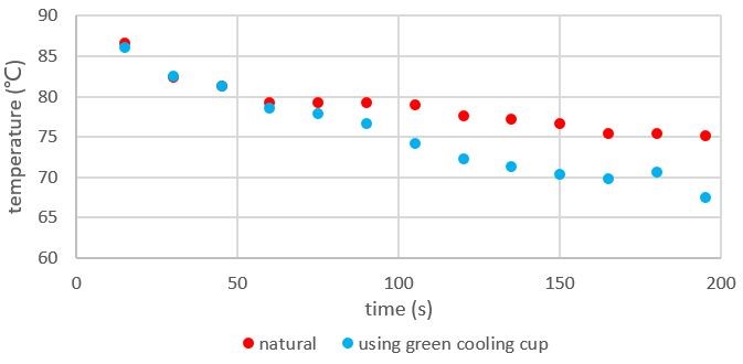
Fig.5 Cooling Performance Result
Conclusion
In this project, the following objectives are achieved:
- Design and optimize the fan system based on real working conditions.
- Realize an auxiliary stir system to enhance cooling effects.
- Conduct measurements and analysis.
- Model and assembly supporters to construct sub-systems into a complete cup.
To improve the performance of the cup, the following things can be done:
- Further modify the shape of the fan
- Optimize the circuit design
- Lower its producing cost
Acknowledgement
We want to express our sincere gratitude to our professor Dr. Qiang Zhang and Dr. Irene Wei, the teach assistants Shijie Zhong, Haonan Luo, Minjia Qian and Xingye Tang, and the material supports from SJTU Global College.
Reference
[1] https://www.wisegeek.com/what-is-green-industry.htm