Student Projects
VE/VM450

Automatic Monitoring and Warning System for the Health Status of Low-voltage Electrical Switches
Instructors: Prof. Chengbin Ma
Team Members: Xinyu Tong,Xiaoxue Zhong,Yiyang Tang,Wen Li,Jin Huangfu
Project Video
Team Members

Team Members:
Xinyu Tong,Xiaoxue Zhong,Yiyang Tang,Wen Li,Jin Huangfu
Instructors:
Prof. Chengbin Ma
Project Description
Problem Statement
Low voltage electrical switches are widely used in smart power grids as key components. However, after a long period of time, due to oxidization and dust accumulation, serious safety accidents are more likely to happen. To both ensure safety and save labor force, an automatic monitoring and warning system on the deterioration of the switch is in need. Our purpose is to design and build an automatic test system including real-time monitoring of switch data, capturing deterioration factors, giving alarm, disconnecting power and recording the parameters of the switch[1].
Concept Generation
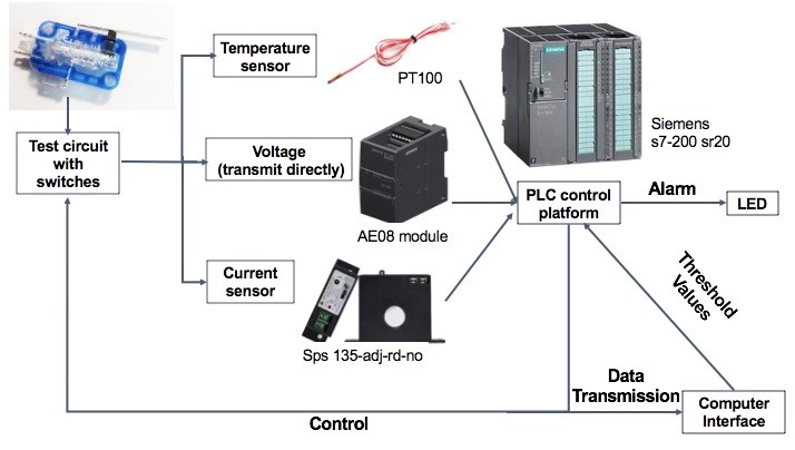
Sub-system concepts are using sensors to capture real-time data as well as the deterioration factors. The PLC control platform controls the whole system and sends signal to both the LED part for alarming and the switch to disconnect power. Data is also transferred and stored for future improvement.

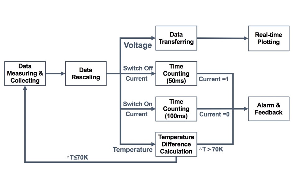
Fig. 1 Detailed structure function

Fig. 2 Concept Diagram
Design Description
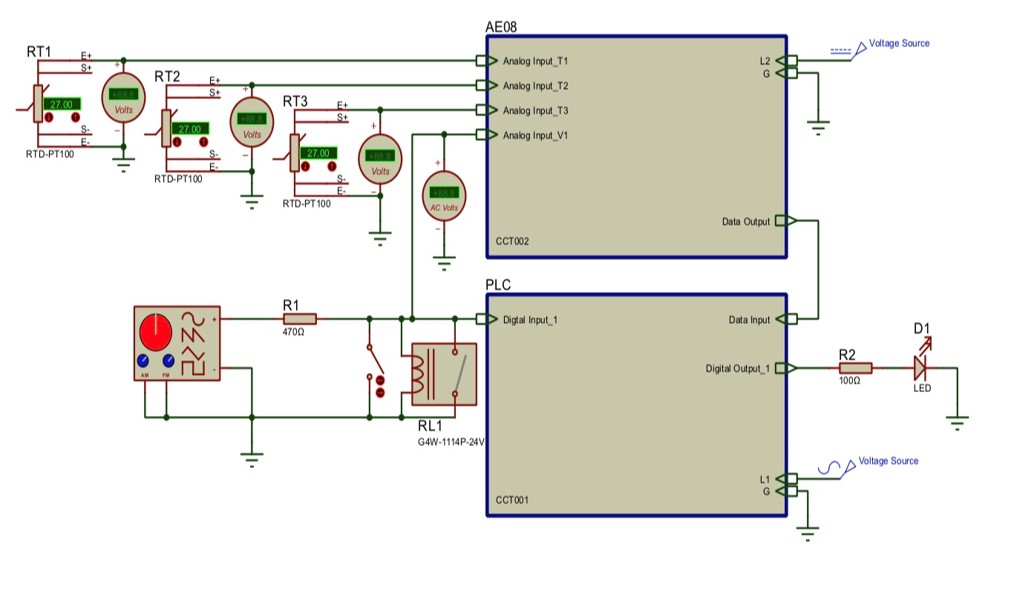
The design connects the switch to different sensors and continuously detect the temperature, voltage and their corresponding transducers. In the control unit, AE08 module receives all the analog data and sends to PLC. PLC controls the whole system and gives the alarm through LED.

Fig. 3 The circuit diagram

Fig. 4 The interface
Modeling and Analysis
For voltage, data is transformed to computer directly and voltage curves are plotted. For current, once signal indicating the switch is off is given, timer is stared in PLC and counts for 50ms. If AC current shows the existence of current, it’ll be treated as abnormality and alarm will be given. For other cases, the timer counts for 100ms and check whether the current exists. For temperature, both switch and environmental temperature in registers are stored and temperature difference is calculated for comparison with the critical value.

Fig. 5 The voltage curve
Validation
Validation Process:
For detection accuracy, we choose sensors which can not only meet the customers’ detection demands but also meet the signal detection precision.
For judgment efficiency, the hardware circuit along with the software we employ ensures that judgement never fails under test environment. A capsulation produced by 3D printing is in need to protect the whole circuit for longer time usage.
Validation Results:
According to validation part, most specifications can be met.
√ Sensor reaction time <50ms.
√ Judgement time <50ms. √ Judgement accuracy >99%.
√ Temperature detection precision <0.5K.
√ Current flow time detection precision <50ms.
√ Voltage detection precision <0.2V.
√ Cost<=3,000RMB.
· Amount of sensors >=11 pcs.
√ means having been verified and · means to be determined.
Conclusion
Circuit design for deterioration trend detection and alarm giving along with software for analysis are achieved to realize our purposes. An interface and a capsulation are designed to make the system more user-friendly. Both accuracy and speed of the detection are very important for automatic test.
Acknowledgement
Sponsor: Shanghai Feili Xuncheng Electric Technology Co., LTD
Instructor: Chengbin Ma from UM-SJTU Joint Institute
Instructor: Chengbin Ma from UM-SJTU Joint Institute
Reference
[1]Development assignment of Shanghai Feili Xuncheng Electric Technology Co., LTD
UM-SJTU JOINT INSTITUTE