Student Projects
VE/VM450

Real-Time Control Platform and Algorithm for An Experimental Flexible System
Instructors: Prof. Chengbin Ma
Team Members: Yanhao Deng, Mengyuan Shen, Huinan Hu, Xinli Zhang
Project Video
Team Members

Team Members:
Yanhao Deng, Mengyuan Shen, Huinan Hu, Xinli Zhang
Instructors:
Prof. Chengbin Ma
Project Description
Problem Statement
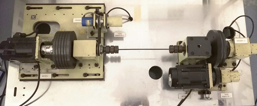
Real-time control is an effective system widely used in today’s industry. This kind of system is of good maintainability and modularity, thus it can be applied in various places. This project is to re-establish a real-time control system on a multi-mass system test bench shown in Fig.1, and develop a better algorithm for this system for teaching and testing.

Fig. 1 Multi-mass system test bench.
Concept Generation
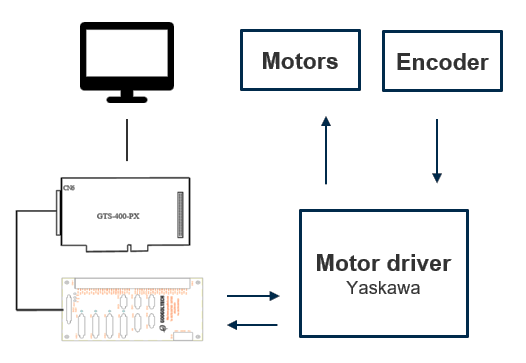
A controller board installed on the PC has relatively lower cost, better performance, and high adaptability compared to an independent programable controller.

Fig. 2 Concept Diagram.
Design Description
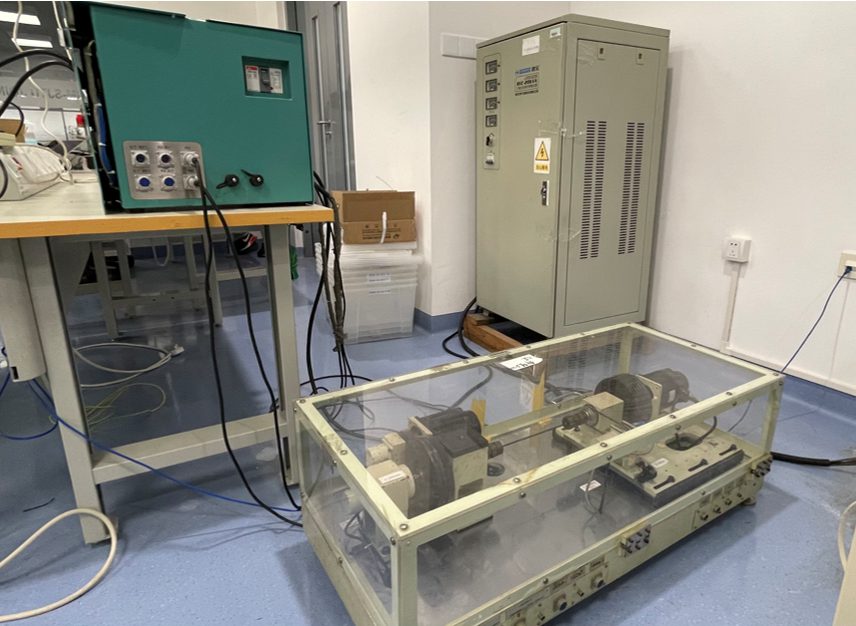
The design uses Googoltech GTS400 as the controller of the system and Visual Studio C++ as the programming language. A terminal board is to connect the controller and driver. One of the motors is to drive the system, and the other is designed to simulate different kinds of disturbances for testing (shown in Fig. 3).
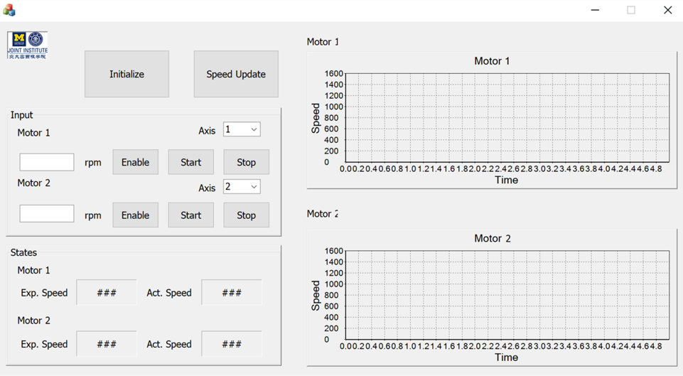
The Windows application has the functions to control the speed and update speed. Data acquired from the encoder is dynamically shown on multiple charts. Besides, the response of the system is automatically calculated and plotted. MFC library is used to establish the exclusive application and UI, to realize the precise and free control of the system in different situations (shown in Fig.4).
The algorithm of the control program is designed based on classic PID control for a more controllable system and better resistance to disturbances.

Fig.3 The whole set-up mechanical system.

Fig.4 Application UI.
Modeling and Analysis
A PID close loop control model shown in Fig. 5 is built to enhance the stability and response speed. The model employs a feedback signal from the encoder to calculate the error and applies a correction based on a linear combination of proportional, integral, and derivative terms to control the input under disturbance. The control algorithm is realized in the C++ program.

Fig. 5 PID Control diagram.
Validation
Validation Process:
200V three-phase alternating current was supplied for the two motor drivers. Then the system could run under control. Different speeds were set in the developed UI and update continuously. The motor would change its speeds accordingly. Meanwhile, the response time was recorded by a timer shown in the interface. To test the ability to resist disturbance, the disturbance motor was turned on at a safe speed. The two motors’ speed were adjusted simultaneously to simulate the disturbance condition, with the same method to record the response time and steady error.
Validation Results:
√ Response time <=1ms
√ Sampling rate >=1kHz
√ Cost <=5000RMB · Steady error <= 1% √ means having been verified and · means to be determined.
Conclusion
A real-time control system can be built by connecting a set of hardware including PC, control card, motor drivers, and motors. An independent user interface is developed based on the MFC function in C++.
The key to achieve the goal of fast response is to set up the PID feedback control system with proper gain parameters. The whole system can be used for purpose of teaching and demonstrating in JI Lab.
The key to achieve the goal of fast response is to set up the PID feedback control system with proper gain parameters. The whole system can be used for purpose of teaching and demonstrating in JI Lab.
Acknowledgement
Instructor: Chengbin Ma
Jigang Wu, Chong Han, Mingjian Li from UM-SJTU Joint Institute
Xiang Hao, Hongfeng Xu, Hanchen Cui, Zhikang Li from UM-SJTU Joint Institute
Jigang Wu, Chong Han, Mingjian Li from UM-SJTU Joint Institute
Xiang Hao, Hongfeng Xu, Hanchen Cui, Zhikang Li from UM-SJTU Joint Institute
Reference
[1] Koulamas, Christos and Lazarescu Mihai, Real-Time Embedded Systems: Present and Future, Electronics, 2018.
UM-SJTU JOINT INSTITUTE